NI003, my 3rd automatic
robot vehicle
Year:
2002-2006 (not done yet)


This is my biggest project, and is also my
diplome-project.
The robot has to be able to: sensing small
obstackles, sensing the sideof the table (end of the ground) and the barriers,
sensing the turning angle, and the path, and also sensing activities in the
room. It has to can moving itself, and the small obstackles, like dices.
Sensors:
-Laser
radar: to sense the obstacles, and barriers.
-Infrared
reflective object sensors: to sense the ground, avoiding the falling down from
the table, which means the ground for the robot.
-MEMS
Accelerometers: to sense the acceleration in two directions, to compute travel
from the starting point.
-Knocking
sensor: it is a microphone, with some circuits, to sense, when somebody drops a
dice.
The
mechanics:

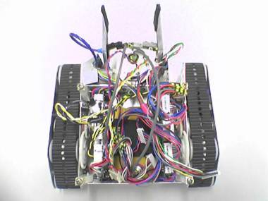
The robot has two caterpillars, because this
way it can turn in place. These caterpillars was made from shoe-sole material,
at home. These have 6 wheels, what not I made, but a turner made on a cnc-lathe
machine. The chassis was made from 1mm thick aluminum plate, at home, with
papercutting scissors!
The cathing arms were made from aluminum
plate, some Lego parts, and cogs from audio casette recorders, and CD-ROMs. The
arm has 4 switches as way-end-sensors.
The
laser radar:
I wouldn’t like to put anything about hat,
because it is possible that I will try some patenting procedures for that
thing. But, I know, this is the most interesting, and most difficoult thing in
this project. Just some things: Ican measure distances, in many directions -i
hope with 3mm resolution- to build a radar image.
The
ground sensors:
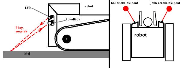

It senses the
reflected and modulated signal from the IR-LED, through the reflection on the
surface of the ground. It senses in two directions, for the better safety. I
use TV remote controller receiver ic-s in the processing circuit. The sensors:
SFH481 IR LEDs, and BPW41 photodiodes. It eats 100mA. But it can be turn off,
because it is not needed when the robot doesn’t move.
Knocking sensors:
Simple dynamic microphone, to hear when
somebody drops a dice. Because it will be a possible application for the robot,
to find the dice, and bring back to the origin.
Accelerometers:
If we can measure the acceleration, we can
compute the speed, with a simple numeric inthegral, with the DSP. If we know
the speed every time, we can compute
the travel way in the same method. Then more simple to compute the position in
a table. So this is navigation. We measure acceleration at the x axis, to
compute linear moving, and measure acceleration in the y axis, to compute it to
angle-acceleration, and then to angular turning.
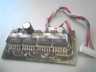
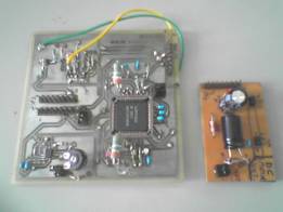
Motor
driver circuits:
I used four pieces of LDM18200Ts from
National. Using these is very easy. This motor driver is in a separate board,
and works in PWM mode. The arm needs just 6-10% duty cycle, but the driver
motors need 20-90%, depending on what do those: turning, or linear moving.

Power supply system:
The robot’s circuits need a lot of vltages,
in numbers of power and noise levels. So there is a separate power supply
board, to produce that. It also does the accumulator-charging.


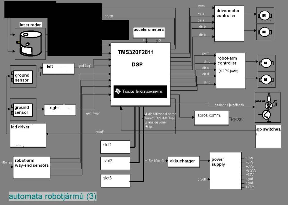
Main control, and the whole electronic
system:
The soul of the robot is the TMS320F2811 DSP
from the Texas Instruments. It runs on 100MHz. The original concept was that
the robot must do everything, without any human intervention, recognize
situations, an find solutions alone. There is an RS232 interface, for testing.
Testing the sensors, the sensor signal processing, an testing the control of
the mechanincs. It have to solve a complex task alone, like to finding the
dices, and bring those back to the origin, where it powered up at the first
time.
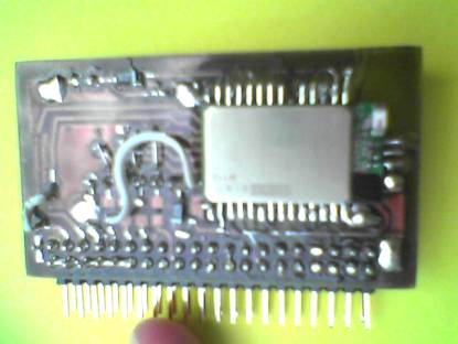
The system’s block diagram: (The black thing is the top secret thing J.)
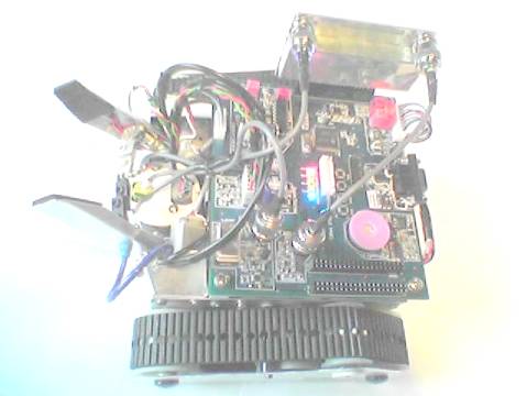
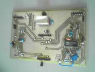
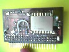
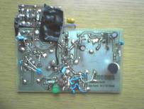
the
mainboard: (the old at left, and the new at right)
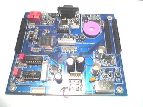

The mainboard is a two layer-board, with
separate power and signal grounds, similar to the systems with analog and
digital grounds. There are both analog and digital, high current, and low
current, sensitive, and noisy circuits. So this is a nightmare about the aspect
of signal integrity, and EMC, but this
makes the work more nice for the designer!
In several years, I designed and made many
printed circuit boards for the project:
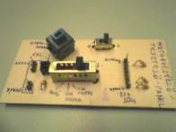


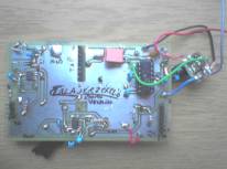

The most of them are only test circuits for the
separated functions of the robot. Some of them are home-made, but the recent
circuits are made by PCB manufacturers.
10.december.2005:
The tests
of the electronics system, and the repair of the hardware are full done, and
works fine. The laser radar is also works well. The semester is ending these
days, so the writing of the software is the following semester’s task. Some
little c programs are written, to control the mechanics, and some sensors. I
want to put these, as drivers, to a software system, with the real
time-operating system, the DSP/BIOS, what I will write. After that, I hope I
will finish the project with the auto-navigation and dice-handling until the
end of the next semester, to put in as a diploma.
16.march.2006:
The DSP’s
ADC does not work well, and the electronics should to redesign to get better,
more recognizable radar images.
2. May,
2006:
I have
redesigned the board, with active filters as front-ends for the DSP’s ADC. The
ADC now works fine and correctly already.
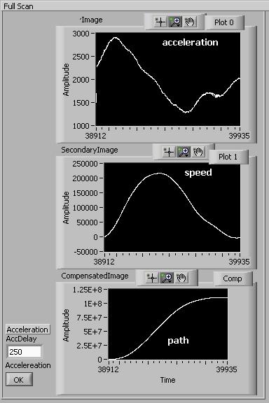
Accelaeration
sensing and speed/path calculating for the robot positioning: The robot is
remote-controlled by commands from the host computer. There are commands about
robot moving, positioning, where the robot’s DSP will calcilate the path during
moving. It is good for linear moving, and for turning around the robot’s center
poing.
Test
acceleration samples, with manual moving test Test
acceleration samples, with automatic moving test
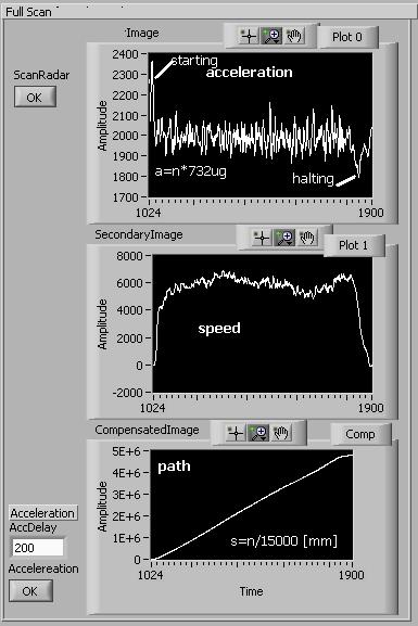
In the
second image, it is visible a vibration during the linear moving period. But,
the expected value of that is zero acceleration (calculated by a substraction
of the offset, the acceleration of the repose state).
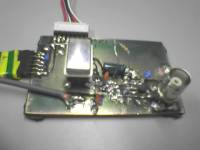
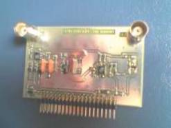
24.05.2006
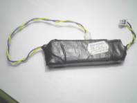
The
Bluetooth interface card has been done.
I work on
the configuring of the Bluetooth module, to enable the robot remote control,
via a radio link.
It took one
and a half days to design and build the card. I have used a WT12 standalone
Bluetooth module from the Bluegiga technologies (and Sero kft).
The
home-made Bluetooth card.
10.06.2006
The robot
works now as a remote controllable version, via Bluetooth, from the PC.
The
automatic control verion (I hope so) will work in the end of the year, or only
next year. I have to finish the radar hardware development, because this is the
key of the automatic control/navigation. It does not work correctly yet.
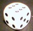
(Where is the dice? This is the big question,
what the robot will try to find out)